Introduction
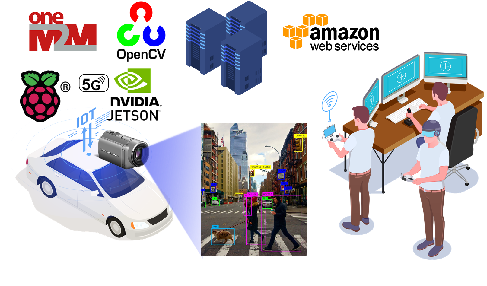
In this project, we are going to build a remote-driving intelligent robot car using single-board computers combined with IoT oneM2M techniques. The car can be controlled by a remote driver through the WiFi or 5G network and sends the camera view as well as the AI-recognized road status information back to the remote user.
We will program on single-board computers, such as Raspberry Pi 4 and NVIDIA Jetson, and develop a remote control system for the robot car. The control system will be built on 5G/LTE IoT networks and AWS/GCP platforms using oneM2M and real-time communication protocols. We will also develop a road status recognition module based on computer vision techniques to assist remote users to take necessary action in real-time. The challenges in this project are:
- Developing a control system over multiple devices/platforms including embedded devices, cloud computing platforms, and desktop computers.
- Developing a oneM2M and real-time communication solution via 5G IoT networks and the Internet.
- Developing a computer vision model on a resource-limited embedded device.
About this project, you can find the source code in this GitHub repository and more information on the project page. We host a web controller and ACME server which allows users to remote control RoboCar and check the container data on the server. In this post, we will show how to build such a system step-by-step.


What You Need
RoboCar uses ARM-based development boards (Raspberry Pi 4 and NVIDIA Jetson Nano), OpenCV, and other industry-standard components to show an applicable example of embedded systems. The system has the following components: motor car control, live video streaming, 5G networking and oneM2M, road status recognition. The detail of each component is shown in the following table.
| Components | Hardware | Software |
|---|---|---|
| Car control | Raspberry Pi 4 model B Robot motor car TB6612FNG motor driver Prototyping board Jumper wires |
GCC, Make |
| Live video streaming | EMEET SmartCam C960 Webcam | Python 3.8+, OpenCV2, AWS |
| 5G networking and oneM2M | SIM8200EA-M2 5G HAT, Straight Talk 5G SIM card | Python 3.8+, SIMCOM driver, GCP |
| Road status recognition | NVIDIA Jetson Nano, Logitech C270 HD Webcam | Python 3.8+, OpenCV2, TensorFlow |
System Architecture

RoboCar mainly consists of three components: a four-wheel motor car, a Raspberry Pi 4 with a 5G HAT, and an NVIDIA Jetson Nano. The motors in the car are controlled by a wheel control module running on Raspberry Pi 4. The module receives control commands from network through the 5G communication module. On the Jetson Nano, the road status recognition module detects traffic lights and stop signs from the video frames, and sends signals to Raspberry Pi 4 through GPIO pins.
We show the structure of RoboCar in Figure 4. The red box shows the Raspberry Pi 4 with a 5G HAT module. Raspberry Pi Model B controls the movements of the RoboCar based on the inputs from a (local or remote) controller. A webcam will be used for monitoring the environment around the RoboCar. The video will be streamed back to the user through the Internet.
The green box shows a Jeston Nano with a USB camera: The USB Camera will be used to capture the images, NVIDIA Jetson Nano will analyze the images and output signals by two GPIO pins: one for traffic light detection, the other for STOP sign detection.
The blue box is a four-wheel motor car which can be controlled by a Raspberry Pi using GPIO pins.
In order to control RoboCar, a laptop is used for accessing the controller web page user interface so that the users can input the instruction commands. More detailed information will be introduced in the following sections.

Motor Wheel Control
We have implemented a local control module on Raspberry Pi 4, which allows a user to log in through the local network and input control commands.
The local controller is running on the Raspberry Pi 4 controlling the motor car. We can input commands to the program through keyboard.
The car can be controlled using A-D-W-X-S commands, which stands for turn left, turn right, move forward, move backward and stop. i and j are used to increase and decrease the speed.
To implement the driver controls of the project which takes the input from the user and performs the specific function on the robot car which can be either or from the listed commands(w,x,a,d,i,j). The given operation is performed for a time period which is 2 secs. The user has an additional functionality of changing the speed which can be controlled by I and j (for speed up and down respectively). The given program is implemented on the hardware with the help of motor driver board and a Raspberry Pi. The Raspberry Pi is connected to a breadboard with the help of T board which in turn gives us the opportunity of different GPIO pins. The given GPIO pins is connected to the motor driver board which acts as an interface between the motors and the control circuits. Motor requires a high amount of current whereas the controller circuit works on low current signals. So, the function of motor drivers is to take a low-current control signal and then turn it into a higher-current signal that can drive a motor. everything can be seen attached to the file at the end.
The code to control the car has been written in C as it provides better functionality and control when we try to deal things which involves hardware. Overall, other than including all the libraries and assigning the pin function to input and output, the program used basic switch case for different commands which in turn use set clear to assign 0 and 1 to the assigned GPIO which in turn convert the motor to on and off depending on the case. At the end I turned all the GPIO pins to input which helps to clear the pins and helps the program to wait for the next input. The code also used get char which helps to take input from the keyboard and convert the signal from keyboard to the car.
RPi4 signals to the motor driver board:
- GPIO pins 12, 13, 05, 06, 22, 23, 3.3V VCC, 5.0V VM, and GND:
- RPi4 pin GPIO12 <-> Motor Driver Board pin PWMA = left motor speed control
- RPi4 pin GPIO13 <-> Motor Driver Board pin PWMB = right motor speed control
- RPi4 pin GPIO05 <-> Motor Driver Board pin AI1 = left motor direction control
- RPi4 pin GPIO06 <-> Motor Driver Board pin AI2 = left motor direction control
(AI1, AI2: 10=>forward, 01=>backward, 00=>stop, 11=>short break) - RPi4 pin GPIO22 <-> Motor Driver Board pin BI1 = right motor direction control
- RPi4 pin GPIO23 <-> Motor Driver Board pin BI2 = right motor direction control
(BI1, BI2: 10=>forward, 01=>backward, 00=>stop, 11=>short break) - RPi4 pin GND, Ground <-> Motor Driver Board pin GND, all three pins ,RPi4 pin 3.3V,
- Logic level: DC Power <-> Motor Driver Board pin VCC RPi4 pin 5V, DC Power <-> Motor Driver Board pin VM, motor power
- The remaining pins of the motor driver board needs to be connected as follows: AO1 and AO2 pins to the left motor, BO1 and BO2 pins to the right motor, STBY pin to 3.3V VCC.
- Motor Driver Board pin AO1 <-> Left motor upper pin = left motor plus (+) terminal
- Motor Driver Board pin AO2 <-> Left motor lower pin = left motor minus (-) terminal
- Motor Driver Board pin BO1 <-> Right motor upper pin = right motor minus (-) terminal
- Motor Driver Board pin BO2 <-> Right motor lower pin = right motor plus (+) terminal
- Motor Driver Board pin STBY <-> Motor Driver Board pin VCC = RPi4 pin 3.3V


oneM2M Communication
The signal/message communication involves 6 components. The communication between components is shown in the figure below.

Initially the Jetson Nano with a camera will detect traffic lights and STOP signs based on the captured images, then it transmits the signal that indicates if there is a traffic light or STOP sign to the Raspberry Pi 4. The Raspberry Pi 4 will analyze the traffic light and STOP sign detected signal and send the detected signal to AWS. After that, Raspberry Pi 4 will issue a STOP signal to RoboCar, if there is a traffic light or STOP sign. Next, when AWS receives the detected signal, it will update the webpage, showing the status of the traffic light and/or the STOP sign. Then, when the PC accesses the web page, the status of the detected signal will show on the webpage.
There are several steps for data transmission from PC to RoboCar. As shown on the right of the figure above, the user enters instructions to the webpage on the PC first, AWS receives the signal, and it will send the RoboCar control signal to Raspberry Pi. After Raspberry Pi receives the RoboCar control signal, it then sends the signal to RoboCar. Finally, the RoboCar will move based on user input instructions.

In order to control the RoboCar remotely from the PC, a user should be able to see the situation around the RoboCar. Therefore, the camera on RoboCar captures the environment in front of RoboCar and streams the video back to PC. Due to the reason that the oneM2M standard may not support media transmission, an independent way for video transmission will be used.

We run a ACME Common Service Entity (CSE) server on AWS infrastructure. The resource tree design is shown in the figure. An AE (RoboCar) is registered the CSE base, and contains mainly three containers: controller, trafficLight and stopSIgn.
The controller container stores the control commands (A-W-D-X-S) sent from the controller WebUI (see next section).
The traffic light and stop sign containers store the true/false data which indicates whether the traffic light and/or stop sign is in the view of RoboCar.
In addition to these three containers, we also add one more heart beat container, which shows the status and timestamp of RoboCar. This allows us to make sure the AE running on the car is working correctly.
These containers are configured to store at most 30 instances with in 1 hour instance age limit.
We have a Python client running on the Raspberry Pi to periodically (every 1 sec) pull the latest controller status from the CSE server and push traffic light and stop sign status back to the CSE server. The controller web UI works in a similar way that pulls the latest traffic light and stop sign status from the CSE server. And every time user click a button or press a key, the web UI will send the command to the CSE server using oneM2M protocol.
Controller WebUI
The controller WebUI is designed for sending the message to acme server when user clicked the buttons on the webpage, and the webpage automatically check the traffic light and stop sign detected signal comes from the acme server then show the detected result on the webpage.

The website can be divided into three parts: website design, sending the control signal to acme server, get the traffic light “acme-onem2m-cse-ix62mzt6pa-uc.a.run.app” and stop sign detected signal from acme server.
In the first part, the web page was designed with html code and it contains 5 buttons, represent “forward”,”backward”, “turn left”, “turn right”, and “stop”, respectively. There are two pictures shown the stop sign and traffic light. The detected results will be shown next to the picture. For example, if traffic light is detected, the message, “traffic light:yes” will be shown next to the traffic light picture.
In the second part, the signal sending uses the post request with JavaScript. By applying the host name: and cse-in/CAmin/control, the data was being sent successfully to the server. These data will be used later for controlling the Robocar.
For the get the detected signal, the get request in JavaScript is applied. The webpage will constantly get the data for acme server once a second, and write the results next to the related picture. Another line of code with function was added to refresh the webpage automatically and get the updated results shown on the webpage.
Live Video Streaming
Video streaming server company selection
The project initially used Amazon’s EC2 virtual computer resource. However, due to the higher costs of network traffic and the nature of the video application, the option was modified during the project to minimize the cost of the project. The new service was provided by the OVH, a french server company, which provides unlimited network traffic for 5$ per month as the service provides all required resources, the project completely moved to the OVH.
VLC video stream viewing vs web page video stream viewing
Once raspberry pi acquires the video image from the USB webcam and uses python’s CV2 module to capture the video and convert the data to the frame object. Once CV2 converts the video traffic to the frame object, the subprocess is created and uses FFMPEG to convert the video data into the RTMP traffic. The RTMP traffic is than hosted into the RTMP server which is located in the US and relay the video signal to RTMP and Web video format by NGINX webserver’s RTMP module.
Video streaming delay/lag/latency reduction
The delay comes from the 3 main parts as follows. “Video acquisition”, “Video transmission from the raspberry pi”, “RTMP Server” and “RTMP client” or “Web client”.
Once the raspberry pi acquires imagery data from the webcam, the CV2 module and FFMPEG module need to pre/pro-process the primitive video data which requires a significant amount of time to de/encode the input and output video data. Once the video is processed, the raspberry pi sends video data to the RTMP server. The RTMP server uses a computer network and needs connection time between the raspberry pi module and the server. The transmission needs a significant amount of time to successfully present video data in the RTMP server. The RTMP server needs to process and post the video to spread the video data to the RTMP users. Currently, due to the limitation of the virtual computing resource, there’s more than 2sec of delay has been observed. Lastly, the network connection time between the server and the client creates a significant amount of time due to its physical distance.
Road Status Recognition
For the RoboCar, we applied Computer Vision by using Jetson Nano to detect the traffic light and the stop sign. There were two ways we tried to implement to Jetson Nano. One way is to use Yolo V5 and the other way is the traditional way with OpenCV. We tried both of the methods and they both had their own drawbacks. And we chose the best performance on the Jetson Nano for this completion.

For our RoboCar, We chose to use the traditional way of computer vision by using OpenCV with Python code. With this traditional way of computer vision, we used color and shape detection to achieve the purpose of object recognition. OpenCV usually captures images and videos in RBG format with integer values ranging from 0 to 255 for RED, BLUE, and GREEN. So this attribute allows us to inform the program of the color range that we are looking for, and once the OpenCV pick up all the color that matches our requirement in the current frame, then we will apply shape detection and which here for stop sign we are specifically looking for a sequence of 8 points that can form a hexagon. And if in the current frame there is an area that matches both the color and the shape requirement, then we will automatically detect it as a stop sign.
For detecting a traffic light, we first detect GREEN and then look for the circle to find the traffic light, and this is when the drawback of this method occurs. Our detection can be really sensitive to light levels due to the fact that color can change based on the different light levels. And for our project, since our traffic light can not be lit up, when the program is trying to look for the dark green that is on the traffic light, it can pick up some other dark color that is near the traffic light, and then it will result in the inaccuracy of our program.
That is when we decided to try using our second method, implementing YOLO v5. YOLOv5 is a model in the You Only Look Once (YOLO) family of computer vision models and it is commonly used in object detection. YOLO v5 is really stable on detecting an object once it is being trained and learning all the datasets that were being fed into YOLO v5. And in fact, we successfully recognized every stop sign and traffic light with high accuracy on the Window system. However, Jetson nano is under the Linux system and the Jetson Nano was preowned by other people, so the system and environment were in conflict with the environment that we are trying to build in order to run YOLO v5. Also, YOLO v5 reduces FPS, so it would be slow in recognition on Jetson Nano. So due to the shortage of time and the shortage of FPS, we finally decided to apply the traditional way for this program.


Installation
Raspberry Pi 5G HAT Setup
Follow the SIM8200EA-M2 5G HAT - Waveshare Wiki to setup your Raspberry Pi.
- Download the latest Raspbian OS
- Run the following commands to install the driver for 5G HAT
sudo apt-get install p7zip-full wget https://www.waveshare.com/w/upload/f/fb/SIM8200-M2_5G_HAT_code.7z 7z x SIM8200-M2_5G_HAT_code.7z sudo chmod 777 -R SIM8200-M2_5G_HAT_code cd SIM8200-M2_5G_HAT_code sudo ./install.sh - Test the 5G HAT is configured correctly with
ATcommandsudo apt-get install minicom sudo minicom -D /dev/ttyUSB2 - Compile the
simcomprogramcd Goonline make - Enable 5G networking
sudo ./simcom-cm
Raspberry Pi Setup
Download the source code from RoboCar GitHub repository to your home directory /home/pi.
git clone https://github.com/tangym/RoboCar.git
Run the run.sh command which checks if the GPIO daemon and 5G simcom-cm are running, and then starts oneM2M client and the motor control program.
./RoboCar/src/run.sh
To run the video streaming module, you need to install OpenCV.
sudo apt update
sudo apt install build-essential cmake pkg-config libjpeg-dev libtiff5-dev libjasper-dev libpng-dev libavcodec-dev libavformat-dev libswscale-dev libv4l-dev libxvidcore-dev libx264-dev libfontconfig1-dev libcairo2-dev libgdk-pixbuf2.0-dev libpango1.0-dev libgtk2.0-dev libgtk-3-dev libatlas-base-dev gfortran libhdf5-dev libhdf5-serial-dev libhdf5-103 python3-pyqt5 python3-dev -y

pip3 install opencv-python==4.5.3.56
Then run the video streaming using the following command.
python3 camera.py
ACME CSE Server Setup
Build a docker image of the ACME CSE server using the following command.
cd RoboCar/src/ACME-oneM2M-CSE/
docker build --no-cache -t acme-onem2m-cse -f tools/Docker/Dockerfile .
docker tag acme-onem2m-cse <my-container-registry>
docker push <my-container-registry>
And run the docker image on your server.
docker run -d -p 80:8080 acme-onem2m-cse
NVIDIA Jetson Nano Setup
Download the car_detection source code on NVIDIA Jetson Nano and run python3 main.py. The traffic light and stop sign indicators should be connected to GPIO 24 and 25 on Raspberry Pi.
User Guide
You can check RoboCar Live for live streaming media information, and use media player (such as VLC) to open rtmp://rtmp-m2m.iamyourjun.com:8080/hls/stream.m3u8 to watch the live video streaming.
To control the RoboCar, go to RoboCar Controller WebUI and click on the arrow buttons or press A-W-D-X-S on the keyboard.